RF shielding enclosures
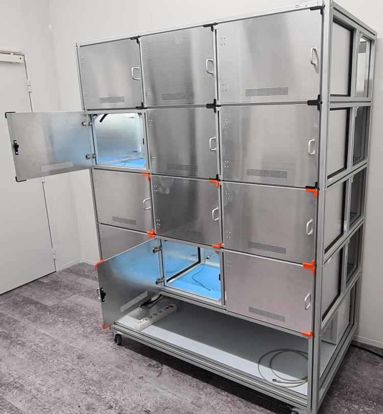
Manufactured 12 mini chambers
I designed a sized rack to hold 12 mini chambers for multiple RF conducted tests.
The goal is to test multiple samples in one place, while also allowing the flexibility to move the rack to any location where engineers need it for testing.
The constraints are as follows:
From a usage perspective, we must maintain the correct dimensions to ensure easy mobility. Additionally, we need to provide enough space inside the chambers for efficient work and allow seamless connections between the sample, its board, and the control PC.
From an RF and mechanical standpoint, we must ensure the mini-chambers are properly sealed, both between them and with the external environment. Furthermore, we must manage operational conditions, such as temperature and humidity, while meeting ESD (electrostatic discharge) requirements to prevent any sample deterioration.
Finally, we must address all of these constraints while keeping the cost extremely competitive, all without compromising on the use of high-quality materials.
First rack cabinet storay
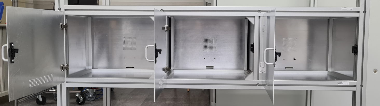
Chamber mechanic design
The chamber consists of aluminum plates that serve as partitions, which are inserted into aluminum frames. Plating and an EMC gasket ensure proper closure, while ventilation is maintained through precisely measured drilled holes, as explained below.
Basic Rule:
To block RF waves in a filter or air duct, the hole diameter must be much smaller than λ/2.
In radio frequency (RF), λ/2 (lambda/2) refers to half a wavelength, meaning the distance considered equals half the wavelength of the electromagnetic signal.
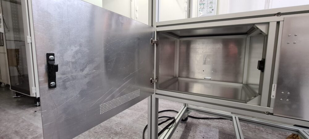
At 5 GHz, λ/2 equals 3 cm, so the holes must be significantly smaller than this value. Typically, we apply a safety margin, limiting the opening diameter to about λ/10 or less, which, in this case, is ≤ 6 mm. Therefore, we chose to drill 2 mm holes and designed the chamber to ensure equal airflow at both the inlet and outlet. As a result, with this hole size, the chamber remains suitable for tests exceeding 8 GHz.
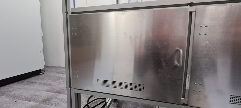
Closed front door with air duct
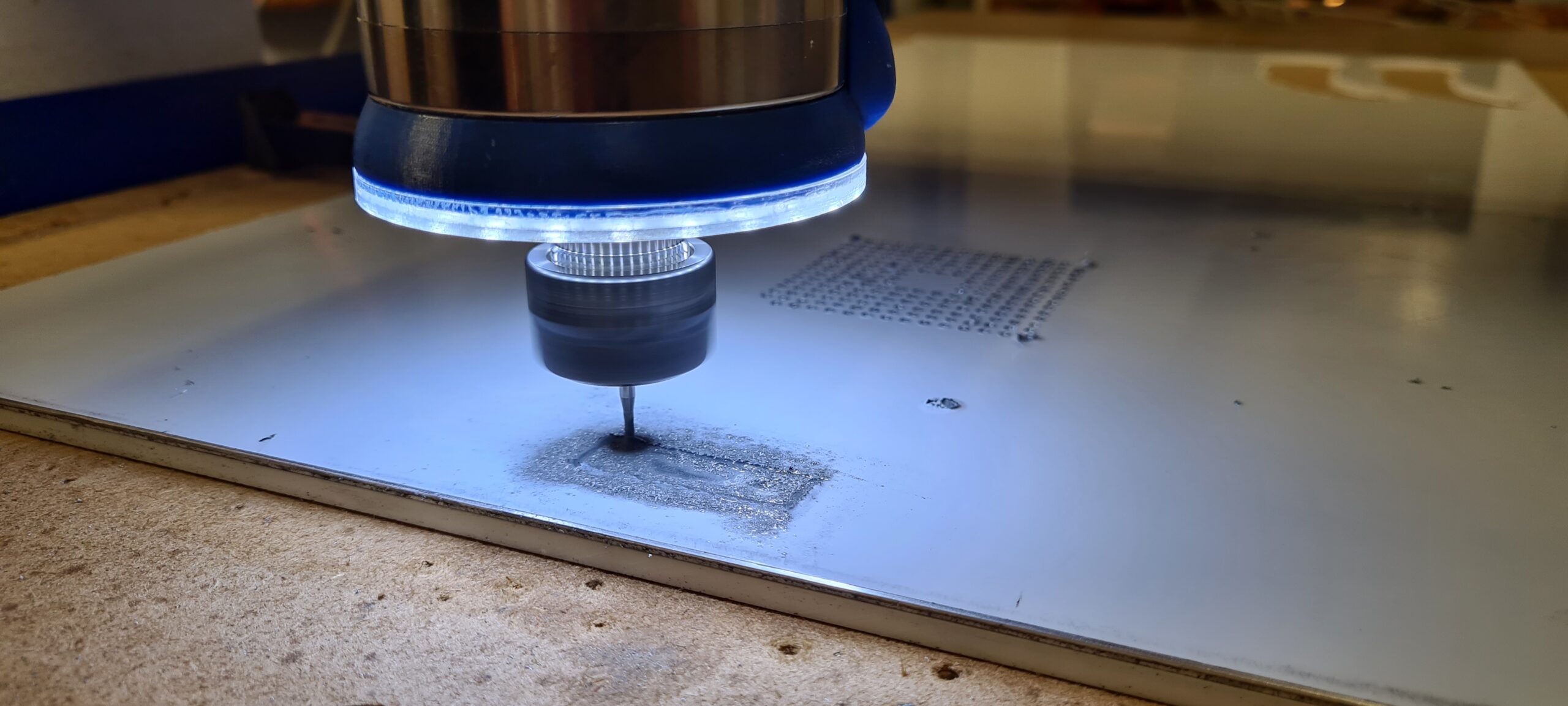
CNC operating on the back plate
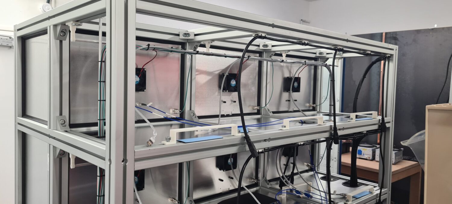
Back shelf storey
The back of the cabinet houses the control PC support and shelves, along with the cable pathway that includes RF cables connected to the switches, high/low electrical power, and network connections.
Additionally, many parts, such as supports and bridles, are 3D-printed. Moreover, fans and RF pass-through components are mounted on the back plates to ensure proper airflow inside the chamber.

Power and command boxes
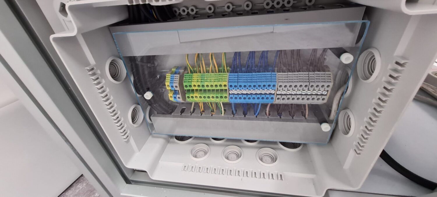
Power supply box
All power supplies, including PCs, RF switches, and network switches, connect to an electrical power terminal block. Additionally, for safety, we place an extra plastic protection in front of the power terminal blocks.
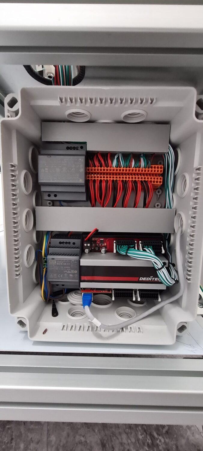
Low voltage connection box
The low-voltage connection box houses the chamber lights and power switch controls. Furthermore, a controlled interface, connected to the network, manages the power switch controls (dry contact).